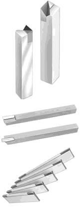
 Unsurpassed shock resistance
- Will not chip or break under normal machining conditions
- Efficient performance through increased feeds and speeds
- Longer tool life
- Just one (1) grade of carbide required for machining all metals.
With MICRO 100® you can attain optimum cutting speeds and feeds, maximum rigidity and virtually no tool deflection. This allows for much higher metal removal rates with far fewer regrinds. MICRO 100® is a “space age,” micro-grain carbide developed for machining high-strength, thermal resistant alloys. The following is a partial list of materials MICRO 100® is best suited for: ALUMINUM — BRASS — BRONZE — COBALT — HASTALLOY — HIGH SPEED STEEL — “M” Series HIGH SPEED STEEL — INCONEL — MARAGING ALLOYS — MOLYBDENUM — RENE 41, 80 & 95 — STAINLESS STEELS (Precipitation — hardening) — SUPER ALLOYS (Iron & Nickel base) — TUNGSTEN — TITANIUM — WASPALLOY — ZIRCONIUM.
HELPFUL HINTS BORING When boring and tools do not meet your expectations, simply grind 5-10 degrees positive top rake, radius nose .010″ to .020″ and lightly hone cutting edge. BOX TURNING When turning hex or square stock, grind a land across the entire face of tool .020″ to .025″. Be sure to lightly hone cutting edge after grind. CUT-OFF Depending on material, often removing and breaking the chip becomes necessary. Here are chip-breaker recommendations: Land = 1 to _ times the feed per revolution. Width = 3 to 4 times the feed per revolution. Depth = .010″ to .015&qu ot;. Always use as much feed rate as possible. MILLING It is important to select the End Mill not only in the appropriate diameter for the job but to also choose the correct size with the number of flutes most efficient for the milling operation performed. In general, the harder the workpiece , the higher the number of flutes should be selected; and the softer the material, the fewer, but wider flutes are required for better chip clearance. After each resharpening, the feather edge on the flutes should be removed with a fine grit hone to avoid chipping. TURNING Rigidity of your set-up and starting your cut at centerline is of utmost importance. A side rake angle of 15 degrees is desirable, and 30-45 degrees for your side cutting edge angles will distribute the cutting force and improve tool life . For heavy interrupted cuts of forgings, use as large a nose radius as possible. For light finishing cuts, grind a 45 degree land .010″ deep across the nose, or radius .015″ – .020″. All chip breakers should have a radius, equal to depth a t rear. WHEN TO SHARPEN
- A change in the color of the chip will usually indicate a dull tool.
- Appreciable wear lands will also indicate the need to sharpen.
- Running dull cutters reduces cutter life considerably.
- A fine-grit diamond wheel is recommended to sharpen, but care must be used to prevent burning of the cutting edge. This could result in cracking of the carbide or flaking of the cutting edge.
- Proper relief angles are necessary for proper performance.
- Typically, 5 to 10 percent of the diameter can be removed without refluting, however, as the O.D. gets ground, the rake angle is reduced, resulting in loss of efficiency in machining.

